Frequently Asked Questions
![]()
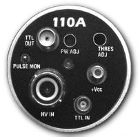 The
"PULSE MON"
test
point gives users the ability to observe a signal
resulting from a neutron or gamma event after it has been
amplified and appropriate wave shaping applied. The
amplified pulse, as measured from the detector, provides
users with a method to observe and monitor the signal
without affecting the performance of the system. The
output impedance of the signal at the
"PULSE
MON"
test point is 50 ohms (about 10kHz),
but capacitively coupled. Applications requiring analog
signal monitoring rather than the TTL OUT signal will
work well with this test point. The signal at the
"PULSE
MON"
can be substituted for the
"TTL
OUT"
if that suits your applications needs
better. Yes, the
"PULSE MON"
test
point is available on each of the PDT100A, PDT110A, and
PDT120A modules.
The
"PULSE MON"
test
point gives users the ability to observe a signal
resulting from a neutron or gamma event after it has been
amplified and appropriate wave shaping applied. The
amplified pulse, as measured from the detector, provides
users with a method to observe and monitor the signal
without affecting the performance of the system. The
output impedance of the signal at the
"PULSE
MON"
test point is 50 ohms (about 10kHz),
but capacitively coupled. Applications requiring analog
signal monitoring rather than the TTL OUT signal will
work well with this test point. The signal at the
"PULSE
MON"
can be substituted for the
"TTL
OUT"
if that suits your applications needs
better. Yes, the
"PULSE MON"
test
point is available on each of the PDT100A, PDT110A, and
PDT120A modules.
and if so, how long?
![]() Each
of the PDT100A, PDT110A, PDT120A and PDT210 products has
a
TTL OUT
signal designed with an internal
50-ohm transmission line driver. Instruments are factory
tested using a 100 meter cable. In some applications,
customers have used these products with cable lengths in
excess of 300 meters with good results.
Each
of the PDT100A, PDT110A, PDT120A and PDT210 products has
a
TTL OUT
signal designed with an internal
50-ohm transmission line driver. Instruments are factory
tested using a 100 meter cable. In some applications,
customers have used these products with cable lengths in
excess of 300 meters with good results.
in high radiation fields?
![]() Our product line has been designed to operate in
high radiation fields. The PDT110A has been tested in
radiation fields in excess of 1Mrad without failure.
Our product line has been designed to operate in
high radiation fields. The PDT110A has been tested in
radiation fields in excess of 1Mrad without failure.
the PDT110A and the PDT120A. Which one should be
used for my application?
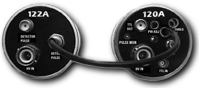
![]() The PDT120A module
performs all of the functions of a PDT110A but also
contains an integral cable that is used only to monitor
additional detectors by using the PDT122A support module.
The integral attached cable on the PDT120 connects
directly to the
PULSE MON
connector of the
PDT122A. The PDT120A/PDT122A combination exists only to
provide users with a viable lower cost solution for
applications that require the monitoring of many
detectors.
The PDT120A module
performs all of the functions of a PDT110A but also
contains an integral cable that is used only to monitor
additional detectors by using the PDT122A support module.
The integral attached cable on the PDT120 connects
directly to the
PULSE MON
connector of the
PDT122A. The PDT120A/PDT122A combination exists only to
provide users with a viable lower cost solution for
applications that require the monitoring of many
detectors.
As an example, suppose you have an application that requires monitoring of thirty-six detectors. Using PDT110A modules, thirty-six modules are required. However, for each PDT120A that is used, generally two PDT122A support modules are used. (Note: Depending on your application, three or four PDT122A may be used for each PDT120A.) For a system requiring thirty-six detectors, twelve PDT122A modules and twenty-four PDT122A's support modules would be used. This has the advantage of simplifying the cable setup, including the cable routing and power supply current requirements. The PDT122A contains only passive components, therefore a power cable is not required.
The PDT122A is substantially lower in cost than a PDT110A. Another advantage, since the PDT122A contains only passive components, is improved resistance to radiation effects.
The disadvantage of the PDT120A/PDT122A combination is its effect on amplifier sensitivity. The PDT122A capacitively loads the PDT120A preamplifier. As PDT122A modules are added, the sensitivity of the PDT120A can be increased by changing the "THRES ADJ" trimpot. For applications requiring the highest sensitivity, the PDT120A/PDT122A could be a disadvantage.
To summarize, for application requiring many detectors, the PDT120A/PDT122A configuration is a cost-effective solution that simplifies your system cabling demands. However, for applications where only a few detectors are used and the highest sensitivity is required, the PDT110A is the answer.
![]()
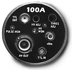 The bias supply is designed to be adjusted via
an internal 12-turn trimpot or by application of an
external dc voltage for use with remote applications. The
voltage range is specified at 0 volts to 2200 volts. The
output current should not exceed 100µA. The bias supply
is designed to bias detectors only and is not designed to
support currents in excess of 50 µA.
The bias supply is designed to be adjusted via
an internal 12-turn trimpot or by application of an
external dc voltage for use with remote applications. The
voltage range is specified at 0 volts to 2200 volts. The
output current should not exceed 100µA. The bias supply
is designed to bias detectors only and is not designed to
support currents in excess of 50 µA.
The PDT100A contains a "HV OUT" SHV connector for use as an external bias supply for interfacing to PDT110A, PDT120A/PDT122A modules, and other detector bias needs.
![]() This problem could very likely be a power supply
problem. Remember, with no counts, a PDT110 requires
about 30mA from the power supply. At 100k counts, the
supply requirement is about 40mA. For counts in excess of
100k, the supply load requirement remains at about 42mA.
RG176 coaxial cable has a resistance of about .32 ohms
per meter. If you are using ten PDT110 instruments
running at a high count level, your supply current for
the system will be about .4 amps. If your power supply
cable is 20 meters, the cable resistance will be 6.4
ohms. A voltage drop of 2.56 volts [(6.4ohms X .4
amps)=2.56 volts] will occur from the supply source to
the PDT instruments. If you are using PDT110A's that
operate on +5volts, the voltage at the amplifier will be
2.34 volts, which is below the power supply
specification. To alleviate this problem, you can use
PDT110A instruments that are designed for +12V operation.
Twelve-volt PDT110A's require less supply current, and
operate over a supply range of 9 volts to 15 volts. If
you are using PDT110A's that require a +5 volt supply,
you must either reduce or eliminate the cable resistance,
or increase the power supply voltage at the source until
the PDT110A instruments receive the correct voltage.
This problem could very likely be a power supply
problem. Remember, with no counts, a PDT110 requires
about 30mA from the power supply. At 100k counts, the
supply requirement is about 40mA. For counts in excess of
100k, the supply load requirement remains at about 42mA.
RG176 coaxial cable has a resistance of about .32 ohms
per meter. If you are using ten PDT110 instruments
running at a high count level, your supply current for
the system will be about .4 amps. If your power supply
cable is 20 meters, the cable resistance will be 6.4
ohms. A voltage drop of 2.56 volts [(6.4ohms X .4
amps)=2.56 volts] will occur from the supply source to
the PDT instruments. If you are using PDT110A's that
operate on +5volts, the voltage at the amplifier will be
2.34 volts, which is below the power supply
specification. To alleviate this problem, you can use
PDT110A instruments that are designed for +12V operation.
Twelve-volt PDT110A's require less supply current, and
operate over a supply range of 9 volts to 15 volts. If
you are using PDT110A's that require a +5 volt supply,
you must either reduce or eliminate the cable resistance,
or increase the power supply voltage at the source until
the PDT110A instruments receive the correct voltage.
![]() The PDT110A instruments are shipped from the
factory with a 50nS "TTL OUT" pulse setting.
The 50nS pulse width can be increased by changing the
trimpot setting. A single-turn trimpot is located just
beneath the hole labeled "PW ADJ." A 50nS pulse
width is not recommended for long cable length. The
"TTL OUT" signal is produced using a 50-ohm
driver that is expecting to see a 50-ohm terminator.
Although it is not necessary, if the 50-ohm coaxial cable
is properly terminated, reflections will be prevented and
the possibility of double pulse counting will be
eliminated. A terminated cable will also help prevent
phase delay problems. If the cable length is less than 15
meters, a cable termination will likely not be required.
When the cable is terminated, the magnitude of the pulse
will be reduced. However, the spectral purity will be
greatly improved, and the pulse will still look like a
pulse, with good rise and fall times.
The PDT110A instruments are shipped from the
factory with a 50nS "TTL OUT" pulse setting.
The 50nS pulse width can be increased by changing the
trimpot setting. A single-turn trimpot is located just
beneath the hole labeled "PW ADJ." A 50nS pulse
width is not recommended for long cable length. The
"TTL OUT" signal is produced using a 50-ohm
driver that is expecting to see a 50-ohm terminator.
Although it is not necessary, if the 50-ohm coaxial cable
is properly terminated, reflections will be prevented and
the possibility of double pulse counting will be
eliminated. A terminated cable will also help prevent
phase delay problems. If the cable length is less than 15
meters, a cable termination will likely not be required.
When the cable is terminated, the magnitude of the pulse
will be reduced. However, the spectral purity will be
greatly improved, and the pulse will still look like a
pulse, with good rise and fall times.
![]() PDT110A instruments have been tested with
several detector types. Since the bias supply and
sensitivity are indirectly related, a lower bias supply
will require a higher amplifier sensitivity. The best
procedure is to set the sensitivity to about 0.04pC (the
factory setting) and adjust the bias voltage until a good
plateau is achieved. For .05pC, a good plateau is
typically achieved at a bias voltage of 1800-1850 volts.
To increase the sensitivity of PDT instruments, turn the
"THRES
ADJ"
trimpot (a 12-turn
trimpot) clockwise. To optimize the sensitivity,
set the sensitivity about midscale. If you're not sure,
set it at approximately six turns below maximum (maximum
is turned all the way clockwise). Then sweep the bias
voltage, looking for a plateau. Increase the sensitivity,
and look again for an improved plateau. Continue doing so
until an improved plateau is found. Typically, the
factory setting is quite good for a bias voltage of about
1800 volts using He3 detectors. This will vary greatly,
however, depending on the detector gain and type of
detector.
PDT110A instruments have been tested with
several detector types. Since the bias supply and
sensitivity are indirectly related, a lower bias supply
will require a higher amplifier sensitivity. The best
procedure is to set the sensitivity to about 0.04pC (the
factory setting) and adjust the bias voltage until a good
plateau is achieved. For .05pC, a good plateau is
typically achieved at a bias voltage of 1800-1850 volts.
To increase the sensitivity of PDT instruments, turn the
"THRES
ADJ"
trimpot (a 12-turn
trimpot) clockwise. To optimize the sensitivity,
set the sensitivity about midscale. If you're not sure,
set it at approximately six turns below maximum (maximum
is turned all the way clockwise). Then sweep the bias
voltage, looking for a plateau. Increase the sensitivity,
and look again for an improved plateau. Continue doing so
until an improved plateau is found. Typically, the
factory setting is quite good for a bias voltage of about
1800 volts using He3 detectors. This will vary greatly,
however, depending on the detector gain and type of
detector.
![]() If you tighten any of the connectors on a
PDT110A, PDT120A or PDT100A instrument with a wrench, you
will most likely damage the connector solder connections.
These connectors will operate quite satisfactorily with
hand tightening. Excessive torque on the connector will
break the connector leads soldered into the printed
circuit board. The connector leads are gold plated brass
and are easily damaged with only a little torque applied.
If you tighten any of the connectors on a
PDT110A, PDT120A or PDT100A instrument with a wrench, you
will most likely damage the connector solder connections.
These connectors will operate quite satisfactorily with
hand tightening. Excessive torque on the connector will
break the connector leads soldered into the printed
circuit board. The connector leads are gold plated brass
and are easily damaged with only a little torque applied.
Products | Features | Dimensions | FAQ's | Warnings | Contact Us | Home
Copyright 2000-2022,
Precision Data Technology, Inc. All Rights Reserved
Designed by
Spidernet
and Maintained by
Tim Eccleston