Application Note: PDT120A
Proper Use of the PDT100,PDT110,and PDT120/PDT122 Neutron Pulse Monitoring Modules - 100A,110A,120A compact neutron monitoring modules designed for high radiation environments connect directly to neutron counters allowing quickly and easy interconnection from 1 to over 100 detectors for digital pulse counting measurements. This new generation of neutron monitoring modules allow new systems to be quickly configured and existing detector instruments to be easily upgraded. The charge sensitive amplifiers are designed for Helium-3,boron loaded, fission chamber, alpha and proton-recoil neutron detector operation. Multiple modules can be easily interconnected providing a single digital counting channel that will process pulse rates exceeding 5 MHz. Engineered in a compact ruggedized aluminum housing that interfaces directly to gas filled detectors, these modules provide an efficient clean solution in difficult environments.
Series 100A,110A and 120A modules provide customers with considerable versatility. This application notes provides users with a basic understanding in the proper using of the 100A ,110A ,120A and 122A instrument.
100A Series Bias Supply - The 100 series modules provide an equivalent feature set to the 110A modules but additionally contains an adjustable high voltage bias supply settable from 0 Volts to 2200 Volts. All modules are configured at the factory for power supply (+Vcc) setting of either +5 volt operation (default) or +12 volt operation.
High Voltage Bias Supply: 0 Volt to 2200 Volt Adjustment Span - The 100A produces high voltages and safety precautions should always be administered when using these instruments. Before applying power, make sure all cables are properly attached and modules are properly fastened to detectors. Do not apply power until modules are properly configured in your application ensuring that the power supply and all cables and detectors are properly connected to earth ground.
The internal bias voltage (high voltage generator) of each 100A series module channels its HV output to two connectors, the "HV OUT " SHV connector located on the top of the module and to the HV PIN ((with suitable filtering applied) located at the bottom of the module which attaches to the detector. The HV PIN interfaces to the gas filled detector and is not available to the operator once connected to a detector. Having the bias supply available at the SHV connector allows customers to use the 100A as the biasing of the 110A,120A,122A series modules, or other applications that might additionally require a HV bias supply. For low count rates, a 100A module can support several 110A modules (4-8).For high count rates (>50K counts/sec), a 100A module supports three 110A modules.
100A series modules are available in three basic configurations,100A (standard),100F (Fixed Voltage), and 100R (Remote control). The 100A is the standard configuration containing an internal twelve turn variable resistor (trim pot) allowing the user control of the high voltage bias supply over a range of 0 to 2200 volts by simply changing the setting on the trim pot. The 100F is nearly equivalent to the 100A,however the trim pot adjustment span is +/- 100 volts about a preset fixed voltage set at the factory. The fixed voltage is determined by the user and units can be shipped with any preset voltage setting between 100-2100 volts. The advantage of the 100F is improved noise, temperature and mechanical vibration performance. Since the adjustment range is +/-100 volts, setting the voltage to .1 volt resolution (i.e..1700.1 Volt!) is easily achievable.
100A and 100F Modules - Both 100A and 100F modules provide access to a internal trim pot via a hole labeled "HV ADJ " located on top of the module. A test point labeled "HV MON " allows users to monitor the high voltage setting as the trim pot is adjusted. When adjusting a 100A module, as the trim pot is adjusted from its lowest level to its highest level (turning the trim pot clockwise using an adjustment tool) a voltage at the "HV MON " test point is observed that spans from 0 to 2.2 volts resulting in a voltage at the "HV OUT "SHV connector spanning 0 to 2200 volts. The same approach is used for the 100F although the voltage adjustment span is greatly limited (+/-100 volts). All 100A units are shipped from the factory with an "HV OUT " setting of 1700 volts which corresponds to a voltage of 1.7 volts at the "HV MON " test point. When monitoring the "HV MON " test point with your DMM meter it is best to connect the LO (or ground) of your meter to the 100 module ground itself (via one of the connector cases) rather than at the power supply source ground. This avoids additional errors resulting from ground current returns. Connecting the meter LO to one of the connector grounds is best achieved using a alligator clip since a ground test point is not provided on the module itself.
100R Modules - The 100R provides remote operation, allowing the user to control the high voltage by applying a precision DC voltage from 0 to 2.2 volts to produce an high voltage output of 0 to 2200 volts. The 100R is shipped with an permanently attached cable (for the remote operation) terminated to a BNC. To control the bias supply voltage, apply a precision DC voltage to the BNC. Be aware that the HV generator of the 100 series is engineered for low noise and excellent long term stability operation. When using the 100R,best performance can only be achieved with use of a low noise and highly stable precision DC voltage. It is best to use a DC source that provide 50 part per million (50 PPM) stability performance and the noise performance should be in the 10 PPM region. Generally, power supply sources will not provide suitable results.
For safety, if the remote cable is not attached to a source, the 100R is designed to produce a low voltage (near zero volts) at "HV OUT ".The input resistance of the remote cable is 10K ohms, high enough that loading of your DC source should not affect performance. The input resistance of the cable alternatively provides suitable protection if you happen to connect the remote cable to a voltage greater than the power supply voltage (+Vcc). The 100R will not be damaged for voltages up to 20 volts applied to the remote cable.
In your application, after the cables and detector(s) have been properly attached to the 100A series modules, apply power to the module. Monitor the "HV MON " test point and adjust either the internal trim pot or the remote DC voltage to obtain the desired "HV OUT " voltage. Use a 5-1/2 digit voltmeter to obtain good monitoring information and allow you to simultaneously monitor noise and stability performance.
Basic Neutron Pulse Counting - The 100A,110A and 120A series of products provide accurate neutron pulse counting in a compact user friendly package. A 50nsec digital pulse from the connector labeled "TTL OUT " is produced each time a bipolar pulse (neutron event) exceeds the discriminator threshold. The 50nsec adjustable digital pulse (adjustability available only on the 110A and 120A modules) is achieved via a variable resistor located beneath a hole labeled "PW " on top of each module. A light-emitting-diode (LED) emits a flash, providing visual indications of detected pulses exceeding the discriminator setting. Control of sensitivity or threshold occurs via a 12 turn trim pot located beneath the hole identified as "THRES ADJ " on top of the module.
 Pulse
Observation -
100A,110A
and 120A modules contain analog pre-amplification and bipolar amplifier
electronics for pulse generation of detector charge events. The amplifier
produces a 0 to 1 volt bipolar pulse which is feed to the "PULSE MON "
test point. The output impedance of the "PULSE MON " test point is 10K
ohms providing effective monitoring using an oscilloscope and impedance loading
of the test point will not affect the performance of the amplifier. Amplifier
gain is set with the "THRES ADJ " trim pot as identified above.
Pulse
Observation -
100A,110A
and 120A modules contain analog pre-amplification and bipolar amplifier
electronics for pulse generation of detector charge events. The amplifier
produces a 0 to 1 volt bipolar pulse which is feed to the "PULSE MON "
test point. The output impedance of the "PULSE MON " test point is 10K
ohms providing effective monitoring using an oscilloscope and impedance loading
of the test point will not affect the performance of the amplifier. Amplifier
gain is set with the "THRES ADJ " trim pot as identified above.
Using an oscilloscope, observe the bipolar amplifier pulse at the "PULSE MON " test point. To simplify the monitoring of the analog pulse, apply the "TTL OUT " digital pulse to the external trigger of the oscilloscope. Remember that each time a pulse is detected by the discriminator, the LED flashes. The LED provides a good troubleshooting aid when monitoring neutron events. With the "TTL OUT " connected to the external trigger of the oscilloscope, cable the "TTL OUT " to the input of a counter and begin counting pulses. Using the 100A module, you can easily increase and decrease the HV supply observing the change in the gain of the amplifier pulses. Use the HV bias as the amplifier course gain adjust and use the "THRES ADJ " trim pot as the amplifier fine gain adjust.
Determining the Proper HV Setting: Obtaining a Good HV Plateau Curve - Use a HV plateau to determine the proper HV setting for a Helum-3 neutron counter. To generate a plateau curve, collect a set of scalar counts ("TTL OUT " pulses) at fixed time intervals at a series of voltage steps. Plot the counts versus HV steps producing a plateau curve. The HV region above the knee of the plateau curve is generally where the detector is operated. Refer to the voltage setting recommended by the detector manufacturer.
Digital Pulse Routing: Digital Summing - 100A,110A,and 120A modules can be daisy-chained by connecting the "TTL OUT " pulses from one modules to the "TTL IN " inputs of another module. This connection sums the digital pulses in an OR ’ed fashion allowing several modules to be daisy-chained, providing a single pulse counting channel. A module interconnection kit (CKB) provides cables and connectors for daisy-chaining modules.
The "TTL OUT " Pulse - The "TTL OUT " uses a 50 ohm source and has been tested with good results using cable lengths in excess of 100 meters. The pulse width is preset at the factory to 50nS.However,on the 110A,and 120A modules, the pulse width can be varied from 40nSec to 500nsec by changing the setting of the trim pot located beneath the hole labeled "PW ADJ " on the top of the modules.
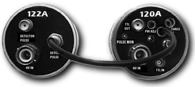
120A/122A Modules: Analog and Digital Summing - The 120A performs the same functions as a 110A or 100A modules related to neutron monitoring but is designed to operate with the 122A support module, a charge collection module.122A modules are easy to setup and operate. Charge events are collected by the 122 module and routed to the 120A module for amplification via the connector labeled "DETECTOR PULSE ".Each 120 module can support input from two to four 122A modules. This interconnection scheme reduces cost, simplifies cabling, allowing a series of detectors to be operated as a single 120A unit.122A modules have no adjustments, do not require a +Vcc (DC power supply) input, and provide the lowest cost solution, requiring only "HV IN " and "DETECTOR PULSE " connections. Note that each 122A module contains two "DETECTOR PULSE " connectors allowing 122A modules to be daisy--chained in a analog fashion. Such a scheme allows both analog and digital pulse summing. The 122A support module channels the analog pulse from the detector to the 120A via a cable that connects to the "DETECTOR PULSE ".Digital summing can occur simultaneously by summing the "TTL OUT " to the "TTL IN " between 120A modules as described above in the Digital Pulse Routing section. Typically, two to three 122A modules would be used for each 120 module.
Factory Options - Due to the wide variety of applications,100A,110A,and 120A modules are customized to a wide variety of needs. Some of the customized applications provided to our customers are state below. These modules provide enormous versatility, and can be customized to your application needs.
|
|
Customers have requested cable options used to replace the test points. Having a cable replace the "PULSE MON " and or the "HV MON " allows users to more simply monitor the analog signal of the neutron event or the HV voltage by connecting directly to their monitoring equipment. |
|
|
100A,110A,120A and 122A modules can be ordered from the factory to interface to gas filled detectors using HN connectors, SHV, or MHV connectors or direct cables. |
|
|
Customized modules have been designed for extremely high radiation environments in excess of 100Mrad. |
|
|
Low power customized modules are available for applications requiring extremely low power. For +5 Volts operation, supply current less than 2mA are available. For +15 Volt operation, supply current less the 1mA are available. |
 PDT120A/PDT122A
modules
are designed to be used in unison. The PDT120A is
equivalent to the PDT110A, but includes a dedicated
integrated cable allowing the PDT120A module to interface
directly to the
"DETECTOR PULSE"
connector of the PDT122A. Several PDT122A instruments
interface to a single PDT120A module, providing users
with a simple, cost-effective approach for multi-detector
monitoring. The cost of each PDT122A module is about half
the cost of a PDT120A.
PDT120A/PDT122A
modules
are designed to be used in unison. The PDT120A is
equivalent to the PDT110A, but includes a dedicated
integrated cable allowing the PDT120A module to interface
directly to the
"DETECTOR PULSE"
connector of the PDT122A. Several PDT122A instruments
interface to a single PDT120A module, providing users
with a simple, cost-effective approach for multi-detector
monitoring. The cost of each PDT122A module is about half
the cost of a PDT120A.
A typical and recommended application uses two PDT122A modules for each PDT120A module. Each PDT122A module has two connectors labeled DETECTOR PULSE . The cable from the PDT120A module connects directly to one of the PDT122A connectors labeled DETECTOR PULSE . A second PDT122A module connects to the-remaining DETECTOR PULSE connector. If desired, additional PDT122A modules can be cascaded for analog summing. Having two DETECTOR PULSE connectors on each PDT122A allows cascading of the analog signals from detector to detector through the PDT122A modules. As PDT122A modules are added, the input to the charge sensitivity preamplifier is capacitively loaded. To increase the sensitivity of the charge-sensitive amplifier, adjust the "THRES ADJ" trimpot setting.
In addition to the two DETECTOR PULSE connectors, an SHV connector labeled HV IN provides the input via the module to bias the detector. Operationally, the PDT122A instrument capacitively collects signals arising from neutron events in the detector, and channels the signal through the DETECTOR PULSE connector, through the cable to the charge-sensitive preamplifier of the PDT120A module. The PDT120A then processes the signal in a similar fashion to the PDT110A. PDT122A modules contain only passive parts, making them ideally suited to high radiation environments.
Operation
PDT120A/PDT122A modules
are designed to be used in unison. The PDT120A is
equivalent to the PDT110A, supporting all of the feature
of the PDT110A, but with one additional feature: a
dedicated cable integral to the PDT120A module allows
direct connection to the "DETECTOR PULSE"
connector of the PDT122A. Several PDT122A instruments can
be interfaced to a single PDT120A module. The
PDT120A/PDT122A combination exits to provide users with a
simple, cost-effective approach for multi-detector
monitoring requirements. The cost of the PDT122A module
is considerably lower than cost of a PDT122A.
Advantages of using PDT122 modules
|
|
PDT122A modules use only passive components so it is ideally suited to high radiation fields. |
|
|
PDT122A modules require a power supply, hence for large systems the power requirements are reduced. |
|
|
PDT122A modules require only a bias supply HV IN , and cables for routing the DETECTOR PULSE signal to the PDT120A. The cable requirements are simple. |
A typical and recommended application uses two PDT122A modules for each PDT120A module. Each PDT122A module has two connectors labeled DETECTOR PULSE. The integrated cable from the PDT120A module is connected to one of the PDT122A connectors labeled DETECTOR PULSE. The remaining DETECTOR PULSE connector is cabled to a second PDT122A modules. If desired, additional PDT122A modules can be cascaded, providing analog summing. Having two DETECTOR PULSE connectors on each PDT122A allow cascading of the analog signals from detector to detector. As PDT122A modules are added, the sensitivity of the charge-sensitive amplifier of the PDT122A will likely need to be increased, since adding PDT122A modules increases the capacitance at the detector head. When PDT122A modules are ordered, a cable is included for interconnecting between PDT122A modules. The PDT122A module contains only passive parts and when connected directly to a detector, provides an SHV connector to bias the detector. The PDT122A collects signals arising from neutron events to channel the signal via the cable to the charge-sensitive preamplifier of the PDT120A modules.
The Charge-Sensitive
Preamplifier, Amplifier and Discriminator
During operation, when a neutron event
occurs within the detector, the charge-sensitive
preamplifier captures the signal resulting from the
neutron event. The signal is further amplified,
integrated and differentiated and a TTL pulse produced by
the discriminator is delivered to the output connector
labeled
"TTL OUT."
PDT120A modules
provide additional versatility to the user by allowing
user control of both the amplifier sensitivity and pulse
width. Generally, the factory setting of the sensitivity
is sufficient to allow good HV plateau curves when 1800
volts is applied to the SHV
HV IN
input connector
using helium-3 neutron detectors. However, when other
detector types are used, or if the HV bias settings can
not be varied, PDT120A modules provide users the ability
to change the amplifier sensitivity easily, obtaining
good plateau results by simply adjusting a trimpot
labeled
"THRES ADJ."
The
"TTL
OUT"
digital pulse is adjusted over a range of
50nS to 500nS by varying the trimpot located beneath the
hole labeled
"PW ADJ."
Other features
that PDT120 modules provide are digital pulse summing, an
LED that provides visual indication of detected events,
and a test point labeled
PULSE MON
allowing users
to view the analog pulse at the output of the amplifier.
It is not uncommon that the TTL OUT signal must drive coaxial cables that are in excess of hundreds of meters. PDT series modules 100A, 110A and 120A provide either a standard "TTL OUT" or a 50-ohm line drive to extended cable lengths.
Digital Pulse Summing: Cascade Operation
Digital pulse summing allows users to interconnect the digital pulses between PDT120A modules. The TTL OUT pulse of one PDT120A module is cabled into the TTL IN input connector of a second PDT120A module. Each module sums the pulses of the TTL IN with the pulses obtained from the detector it is monitoring. If a TTL signal is not applied to the "TTL IN" input connector, no summing action occurs. The benefit of summing digital pulse is apparent by requiring only one signal cable route to the neutron coincidence counter. The TTL pulse width is factory set and the user has the option of specifying a range between the limits of 50nS and 500nS with a default of 50nS. The amplifier sensitivity can be changed by the user but is set at the factory to achieve good plateau results at a bias voltage setting of 1800 volts when using helium-3 detectors.
Electrical Specifications
|
|
Count Rate: >10M count per second |
|
|
Pulse Pair Resolution: 400nS |
|
|
Operating Voltage: for +5 Volts operation: +4.75 to +6 Volts; For +12 operations: 9 to 18 volts. |
|
|
Operating current: No counts: 30mA typ; 100Kcounts: 40mA |
|
|
Temperature: -55 to 85 Degrees Centigrade |
|
|
Radiation Resistance: >1Mrad |
|
|
Warranty: 1 Year |
Products | Features | Dimensions | FAQ's | Warnings | Contact Us | Home
Copyright 2000-2022,
Precision Data Technology, Inc. All Rights Reserved
Designed by
Spidernet
and Maintained by
Tim Eccleston